Case Study: CFD-Driven Ventilation Design for a Battery Rack System
- Jun 21, 2025
- 2 min read
Project Summary
Deratec was engaged to optimise the ventilation system of a battery rack enclosure experiencing high thermal loads during fast charging cycles. Using Computational Fluid Dynamics (CFD), we tested and compared ventilation layouts to ensure the system remained within safe temperature limits — all without costly physical prototyping.
Objectives
The battery enclosure measured 1500 mm (L) × 600 mm (W) × 2300 mm (H) and could reach up to 5000 W of heat during peak 4C charging. The design challenge was to prevent overheating while ensuring even airflow inside a compact, fully enclosed rack.

Our CFD Approach
We modelled two forced ventilation layouts using real fan data (Rittal SK series):
Case 1: Rear-lower inlet filters with two wall-mounted exhaust fans

Case 2: Front-bottom inlets with one roof-mounted exhaust fan
CFD was used to simulate airflow, temperature distribution, and pressure fields under the worst-case 4C thermal load.

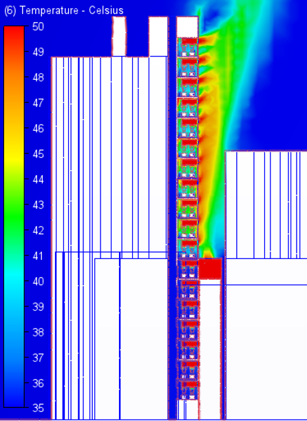
Results
✅ Best Configuration: Case 1 – Wall-Mounted Exhaust Fans
This setup consistently maintained internal temperatures below 45°C, even under 4C operation. It created a stable negative pressure, drawing cool air from the rear and exhausting hot air effectively from the top sides.

🔺 Alternative: Roof-Mounted Fan (Case 2)
Although simpler, the roof-exhaust layout led to heat stagnation near the top, with max temperatures reaching ~50°C.

Conclusion
This case study highlights how CFD simulation helped our client choose the right fan configuration before installation — saving time, cost, and energy. A well-designed ventilation system not only ensures battery safety but also extends equipment life.
If you're designing enclosures for batteries, electronics, or critical equipment — we’re here to help.
👉 Contact Deratec for CFD-driven thermal solutions.


Comments